Chrysler may not have realized the impact on the performance industry that occurred when the first Gen III Hemi rolled out of the production line in 2003. Like a tsunami that starts small but builds momentum and force as it travels, the Gen III Hemi has advanced the lineage from its Gen II cousin and planted the Mopar flag firmly at the top of Horsepower Hill. Everybody else is now trying to play catch up.
If you are a Chrysler fan or perhaps just an admirer of unadulterated horsepower, then the nicknames like Apache, Hellcat, Demon, and Redeye are no doubt familiar. This story intends to fill in the many Gen III details that have laid the foundation for these horsepower heroes. For each lucky soul who can aspire to own one of the 1,025-horsepower Dodge Challenger SRT Demon 170s , there are hundreds, if not thousands who will take advantage of the incredibly powerful opportunities afforded by the Hellcat’s normally aspirated cousins. They are a heady bunch!

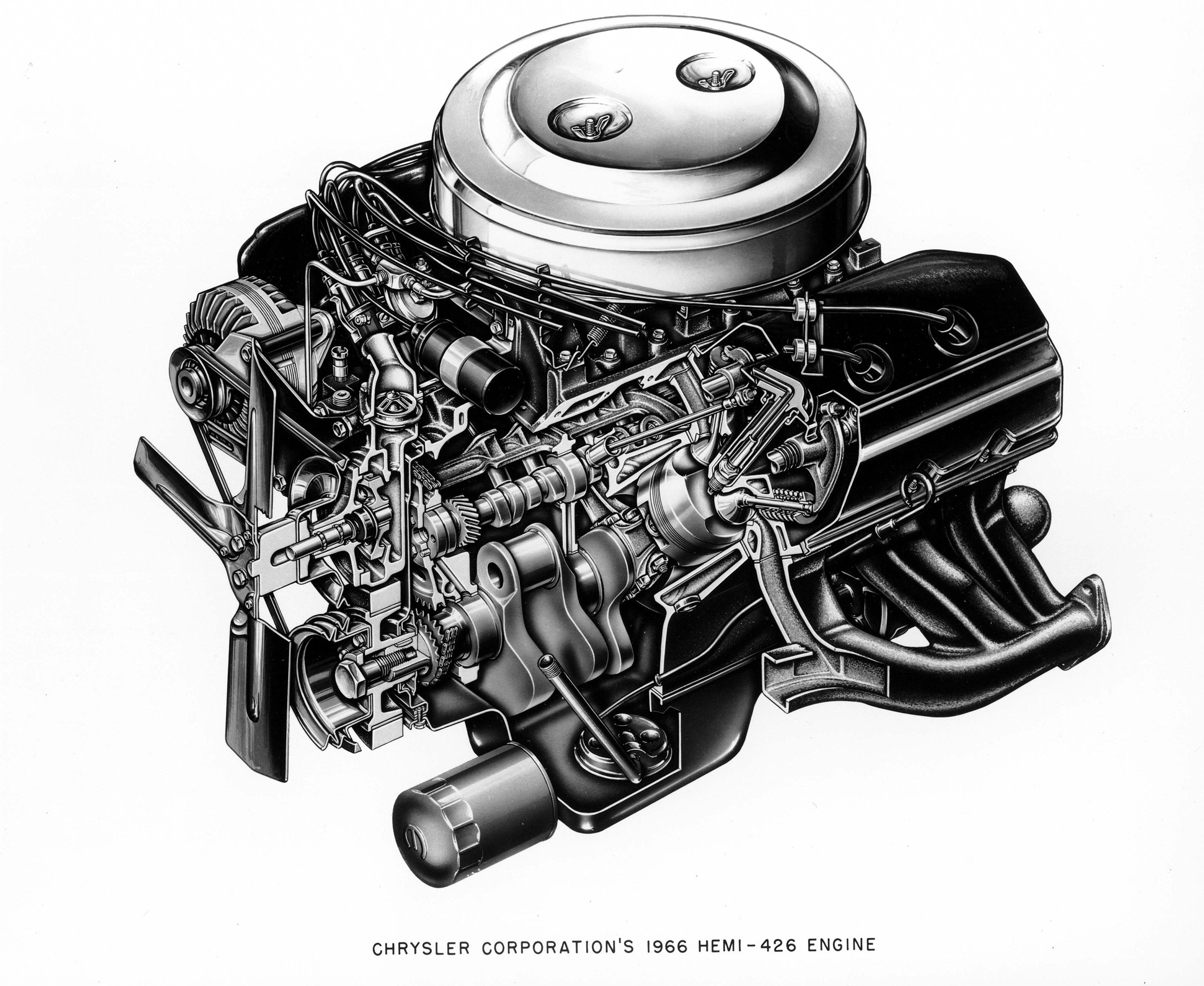
This is a Chrysler drawing of the engine that really put the Hemi name on the map – the 1966 Street Hemi. The original appeared in 1951 as a 331ci Chrysler FirePower engine that eventually evolved (amid radical changes) into the Gen II and now the Gen III version. The original hemispherical chamber concept evolved from an experimental aircraft engine designed by Chrysler at the end of WWII.
For the sake of an acknowledging nod to history, the first Chrysler Hemi V8 appeared in 1951 in Chrysler full-size cars. Dubbed the FirePower, it displaced a mere 331ci. It later grew into the 392ci variant made famous by virtually every early Top Fuel drag car in the country. The Gen II version appeared in 1964, with names like Richard Petty and Keith Black, among many others, making the “Elephant” notorious as a Race Hemi, quickly followed by the 426ci Street Hemi with its expansive chrome valve covers that gave many a stoplight racer immediate pause. Suddenly that easy target in the lime-green ‘Cuda was no longer easy prey.
After going dormant at the end of 1971, the Hemi re-emerged as the 5.7L Gen III in 2003 in Ram trucks, followed quickly in passenger cars. These first 5.7L engines immediately enhanced the Hemi brand with a cast iron block and aluminum heads. Chrysler engineers experimented with a production aluminum block to shave over 100 pounds but studies concluded that the potential loss of cylinder head seal quality with larger bore engines combined with a four-bolt head pattern wasn’t worth the risk versus the weight reduction. There are, of course, multiple aftermarket aluminum blocks available through Mopar Performance should minimizing weight be worthwhile.
Despite the inherent width requirement of the Hemi’s opposing valve orientation (just look at the expansive Gen II valve covers), the Gen III is not excessively wide which makes engine swapping much more attractive. As we’ll see once we dive into the engine’s details, the 5.7L engine continues to this day and has been accompanied by larger 6.1L, 6.2L, and 6.4L cousins.
The key to the Gen III Hemi’s powerful image is tied directly to the cylinder heads. There are multiple production versions as we’ll see but increased cylinder head flow, complemented by the Hemi’s large valves and revised, twin-plug combustion chamber have all contributed to making this engine a serious contender with an awesome punch. Then just to inject steroids into this plan, the Chrysler clan added a production supercharger to the 6.2L engine, creating first the Hellcat, which was quickly followed by Demon and Redeye variants that have singlehandedly established the high watermark for production engine horsepower.
For engine geeks, it’s the details that make the difference, so we’ll attempt to deliver as many of the important internal engine specs as possible. The Gen III Hemi has evolved since its debut in 2003 and you’ll need a scorecard to keep track of what parts fit which variant. This will be our focus, bringing as much information to the table in one place as possible. So let’s get this hemispherical ball rolling, shall we?
ENGINE BLOCKS
If all roads lead to Rome, then it’s also true that all production Gen III Hemi blocks are iron. Aftermarket aluminum blocks do exist through Mopar Performance in various bore sizes, but all production blocks are of the ferrous metal persuasion. Let’s start with the basic configuration. Bore spacing is a critical component that is one of the first decisions that is made when designing a new engine. A greater distance between the bores offers the real estate to increase bore size for massive displacement but this also increases the engine’s overall length.
The Gen III bore spacing is a conservative 4.46 inches, which limits the maximum bore size to roughly 4.100 inches, leaving a thin sealing space for the head gasket between cylinders. There are aftermarket aluminum blocks that boldly expand the bore to 4.185, but this is considered the maximum. Deck height is another important factor since this helps determine the engine’s overall width. The Gen III’s taller 9.25-inch deck height does allow for a longer stroke which we’ll address in the crankshaft section. It has also become apparent that Gen III blocks may vary slightly with regard to deck height, but that will require further research to itemize.
The block is designed around an extended skirt configuration that places the oil pan rail below the bottom of the main caps. This allows the use of small lateral or cross-bolt fasteners to tie into the main caps, adding strength. This adds mass but also minimizes cap walk under high-load applications.

The most noticeable feature of the Gen III Hemi block is the relocated cam centerline that is a full inch taller than previous Chrysler pushrod V8 small-block wedge engines. This shortens the pushrod length and provides plenty of clearance between the cam and stroker crankshaft. This is an early (pre-VVT) 5.7 block.
Perhaps the Gen III’s most distinguishing enhancement is its raised camshaft location. Compared to the previous generation small-block, the cam has been moved more than 1 inch farther from the crankshaft centerline. This not only allows for a larger 57mm cam journal diameter but also reduces the pushrod length, not only adding inherent strength to the valvetrain but also increasing clearance for a stroker crankshaft. With the Hemi valve orientation, the lifter bores are splayed differently than a traditional wedge engine with both pushrods entering the head at a very flat angle.
Perhaps the most critical spec that most interests engine builders is the bore size. As our accompanying chart shows, the Gen III block has progressed from its original 3.917-inch to as large as 4.090 for the 6.2L Hellcat and 6.4L Apache. Chrysler’s recommendation for maximum overbore is limited to 0.020 inches.
The heads are retained with essentially a four-bolts-per-cylinder head bolt pattern with two additional small bolts at the top to seal the upper portion of the head. Other interesting additions include piston cooling jets that are located at the top of the main webbing to direct oil onto the backside of the pistons in an effort to reduce piston crown temperature. These piston cooling jets are only included on the SRT 6.1L, SRT Apache 6.4L, SRT Hellcat/Demon/Redeye 6.2L supercharged, and the 6.4L engines. These jets are not used in 5.7L engines. The 6.2L supercharged Hellcat engine required some minor upgrades to the main cap fasteners and revisions to the piston cooling jets but otherwise the block is the same.
The most common block in service is the 5.7L that has continued since 2003. In 2009, Chrysler added Variable Cam Timing (VCT) and the Multi-Displacement System (MDS) that drops four cylinders out of operation during low-load situations. We’ll discuss both in more detail in the valvetrain section. These systems did require major revisions to the cylinder block to accommodate which makes parts swapping a bit of a challenge. The biggest change is to the front of the block in the cam drive area in order to create room for the thick cam drive sprocket and phaser.
Of important note for engine swappers, the bellhousing bolt flange on the Gen III is the same as the older Chrysler small-block with the exception that the top, center bolt was eliminated on the new engine, leaving six retaining bolts. This makes trans swapping easier.
Because the Gen III is used in both trucks and passenger cars, the starter motor switches positions based on the vehicle. Truck applications place the starter on the left or driver side of the block while passenger car engines move the starter motor location to the right or passenger side of the engine.
CRANKSHAFT
Most Gen III Hemi cranks are nodular iron. All 5.7L cranks are nodular while the SRT 6.1L, supercharged 6.2L Hellcat/Demon/Redeye, 6.4L Apache 392, and 6.4L Big Gas Engines (BGE) cranks are forged steel. The iron cranks are quite strong and capable of handling normally aspirated power roughly up to 700 hp. All Gen III Hemi factory cranks are internally balanced.
According to the information we’ve found, Chrysler also upgraded the nodular crank with the change to VVT in 2009, adding strength with minor changes to rod journal fillets and other changes, so it would appear that a ’09 and later engine would be a wise choice for a performance build.
The VVT cranks also employ a longer tapered area ahead of the Number One journal. This longer taper is used to space the crankshaft timing gear forward. This is required to line up the gear with the relocated camshaft gear that accommodates the variable valve timing (VVT) wheel.
(Left) All 5.7L Hemis spin a nodular iron crank while the larger displacement engines all enjoy the much stronger forged crank. There’s also a difference between the early non-VCT cranks and the later versions. This is an early 5.7L crank with a short tapered section just in front of the Number One main. Later VCT engines extend this tapered nose 0.460-inch to accommodate the VCT components on the cam drive. (Right) Gen III Hemis uses two separate half-round thrust washer inserts that are placed between the bulkhead and crank with tabs to hold them in place. These are held in place once the crank is installed. The arrows point to lubrication slots that should be placed facing the crankshaft.
Stroke is the other half of the displacement equation and despite the four different Gen III displacements, there are only two production stroke lengths – 3.58- and 3.72-inches. The 6.4L engine enjoys the longer stroke while the remaining engines all use the shorter arm. This, of course, offers the aftermarket a wide variety of opportunities. We’ve included a stroker crank chart that lists most of the stroker options as well as their displacements.
There are other subtle differences in the various nodular iron production crankshafts. The early 5.7L and 6.1L engines (2003-’08) employed a 32-tooth crankshaft crank signal or shutter wheel while later engines upgraded to a 58-tooth wheel. Both are bolt-on components so conversions and upgrades are easy. The crank sensor also changed with the increased tooth count, so it’s important to match the crank sensor to the shutter wheel. Chrysler then updated its ECU in 2013 which required yet another change to the reluctor wheel that narrowed the gap for the “missing” tooth. So it pays to know which crank wheel to use. We found this information on Molnar Industries website and they offer all three versions for stroker crankshafts. The crank sensor is located on the passenger side of the block behind the starter motor.
Journal sizes for both nodular iron and forged steel cranks are also the same at 2.56 inches for the mains and 2.12 inches for the rods. This makes it relatively simple to add a stroker crank to build a larger displacement 5.7L for example since the journal sizes remain constant throughout the entire Gen III line.
As a point of reference, all supercharged Hellcat 6.2L cranks enjoy induction hardening on the main and rod journals to improve strength in anticipation of the increased load from the supercharger.
PISTONS
Current technology has upgraded the old cast aluminum piston with a shot of silicon to create a hypereutectic version that offers some strength advantages. Only the supercharged Hellcat and its variants use a forged piston so all the remaining production Gen III engines use a hypereutectic style.
The 5.7L pistons are especially well-designed and are actually quite light relative to their strength. Taking advantage of their small bore, a 5.7L piston only weighs about 415 grams while a Speed-Pro LS1 GM piston is closer to 450 grams.
Early 5.7L versions came with pressed pins while later engines in all four displacements have come with full floating wrist pins. Apparently, there are some exceptions to this rule with some 6.4L engines that come with pressed pins but all SRT variants include full floating pins. Regardless of pressed or floating versions, all Gen III Hemi wrist pins except the SRT 6.1L measure 0.946-inch, although lengths will vary. The 6.1L exception uses a 25mm pin that equates to 0.984-inch.
Early 5.7L engines were initially fitted with 1.5mm / 1.5mm / 3.0 mm ring packages. The top two rings are thinner than 1/16-inch ring (1.5mm = 0.585-inch vs 0.0625-inch for 1/16). With the redesigned VCT engines starting in 2009, these pistons were fitted with a 1.2mm / 1.2mm / 2.0mm ring package. This creates a top ring that is only 0.0468-inch thick – just slightly wider than what was once considered a top-tier race engine ring package at 0.043-inch. To put this in perspective, the previous generation 360ci engines used a 5/64-inch top and second ring that is equal to 0.078-inch thick, which is just slightly less than twice the thickness of the current 1.2mm ring.
This thin-is-in effort is aimed at minimizing internal engine friction and improving bore conformability. This is especially true with the 2.0mm oil ring package. Oil rings generate the greatest amount of sliding friction since their job is to remove the oil from the cylinder wall. The latest generation of oil rings has substantially reduced the amount of sliding friction created. yet still offers excellent oil control.

For potential stroker applications, the piston may have to be notched as this Diamond piston has been in order to provide reluctor wheel clearance.
CONNECTING RODS
Connecting rods don’t get a lot of attention yet the big end of the rod is the most highly stressed component in an internal combustion engine. All Gen III Hemi rods are powdered metal. These are still forged, but are generally considered not as strong as a conventional forged connecting rod.
It’s worth looking more closely at this style rod that has become popular with OE manufacturers. One advantage is that the rod is forged and then instead of cutting the cap and machining the big end, powdered metal rods utilize what is called fractured cap technology where the cap is essentially broken or snapped off. The resulting jagged rod cap surface is used to firmly position the cap. Through bolts are also employed instead of studs and nuts to secure the cap.
While this effort reduces manufacturing costs, these rods cannot be resized or rebuilt in the traditional fashion where the flat cap surface is milled to undersize the big end so it can be honed back to the proper inside diameter. The fractured cap mating surface prevents this procedure.
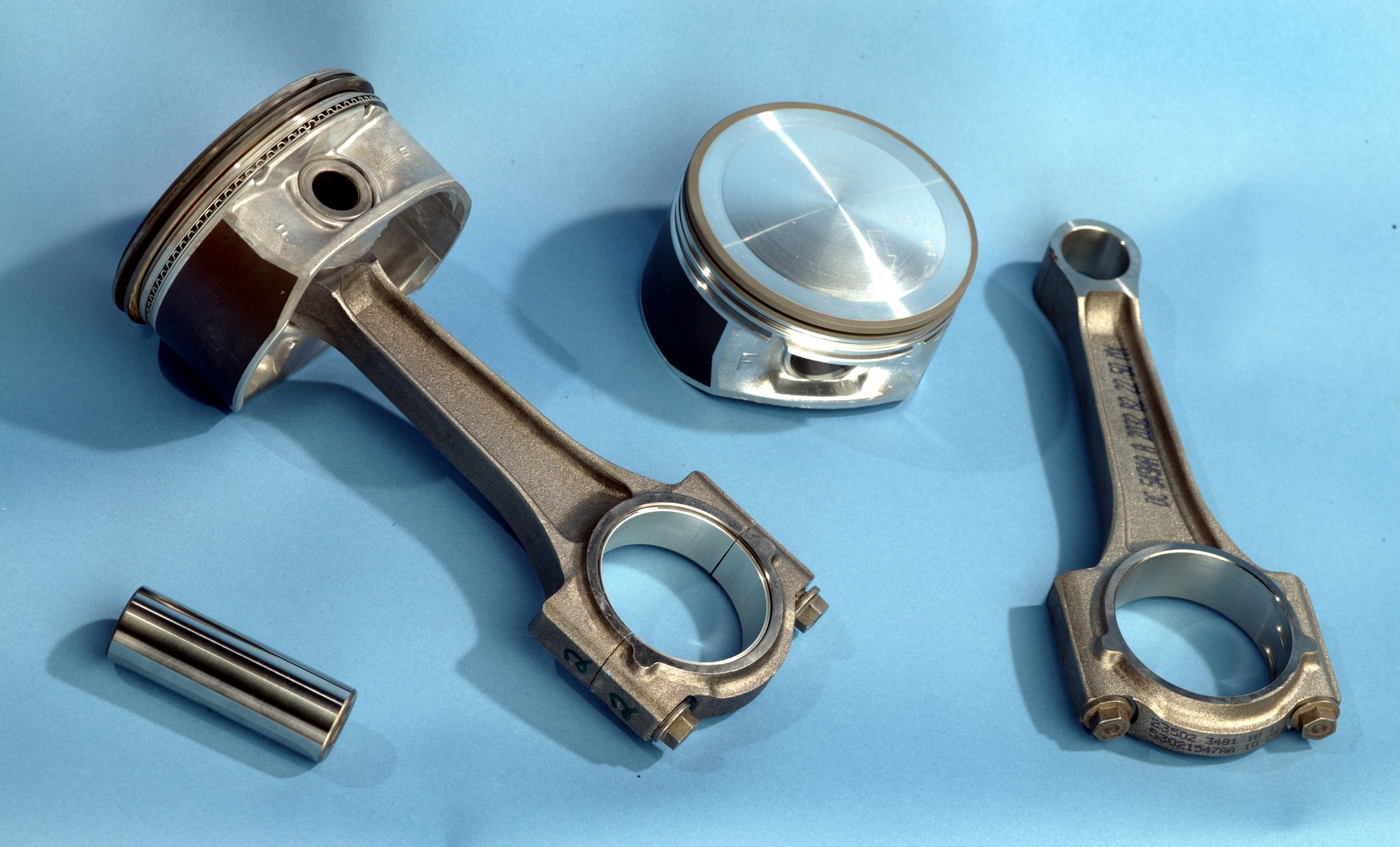
This photo is of an early 5.7L rod and piston combination. Note the smooth rib on the lower rod cap on the connecting rod. Chrysler upgraded to heavy-duty rods in later engines and can be identified by a pair of forged-in tabs on the cap. All factory pistons also come with an anti-scuff coating on the skirts.
All of this makes resizing these rods much more difficult and really emphasizes that if new rods are required for a performance engine build, it is often best to look at investing in a more traditional 4340 aftermarket forged rod that is not only inherently stronger but also often utilizes far superior ARP rod cap bolts. Best of all, all of these rods can be purchased at an attractive price.
Later Gen III Hemis starting in 2009 benefited from a factory-redesigned rod that can be easily interchanged with earlier engines. This strengthened rod can be identified by two small tabs extending from the center bottom of the rod cap compared to early rods that feature a smooth surface across the cap. Of the two designs, the ’09 and later rod is interchangeable with earlier engines and is the more desirable of the two. The one exception is that supercharged 6.2L engines were blessed with improved alloy rod forgings fitted with ARP rod bolts to increase durability.
The majority of production Gen III Hemi engines use a standard 6.24-inch connecting rod length with a wrist pin diameter of 0.945. However, when contemplating converting to aftermarket pistons, keep in mind that many are available in alternative wrist pin diameters. This can get confusing if close attention is not paid to the details. Purchasing a set of aftermarket pistons with a 0.927-inch pin will not be compatible with a production Gen III rod with a 0.945-inch wrist pin.
The lone exception to the 6.24-inch connecting rod length is the long-stroke 6.4L Apache that uses a slightly shorter 6.200-inch connecting rod. This shorter rod is necessary to position the wrist pin away from the oil ring. Aftermarket performance pistons on stroker applications often will push the wrist pin into the oil ring which requires a support rail. OE applications shun this approach, necessitating the shorter rod to create the clearance.
CYLINDER HEADS
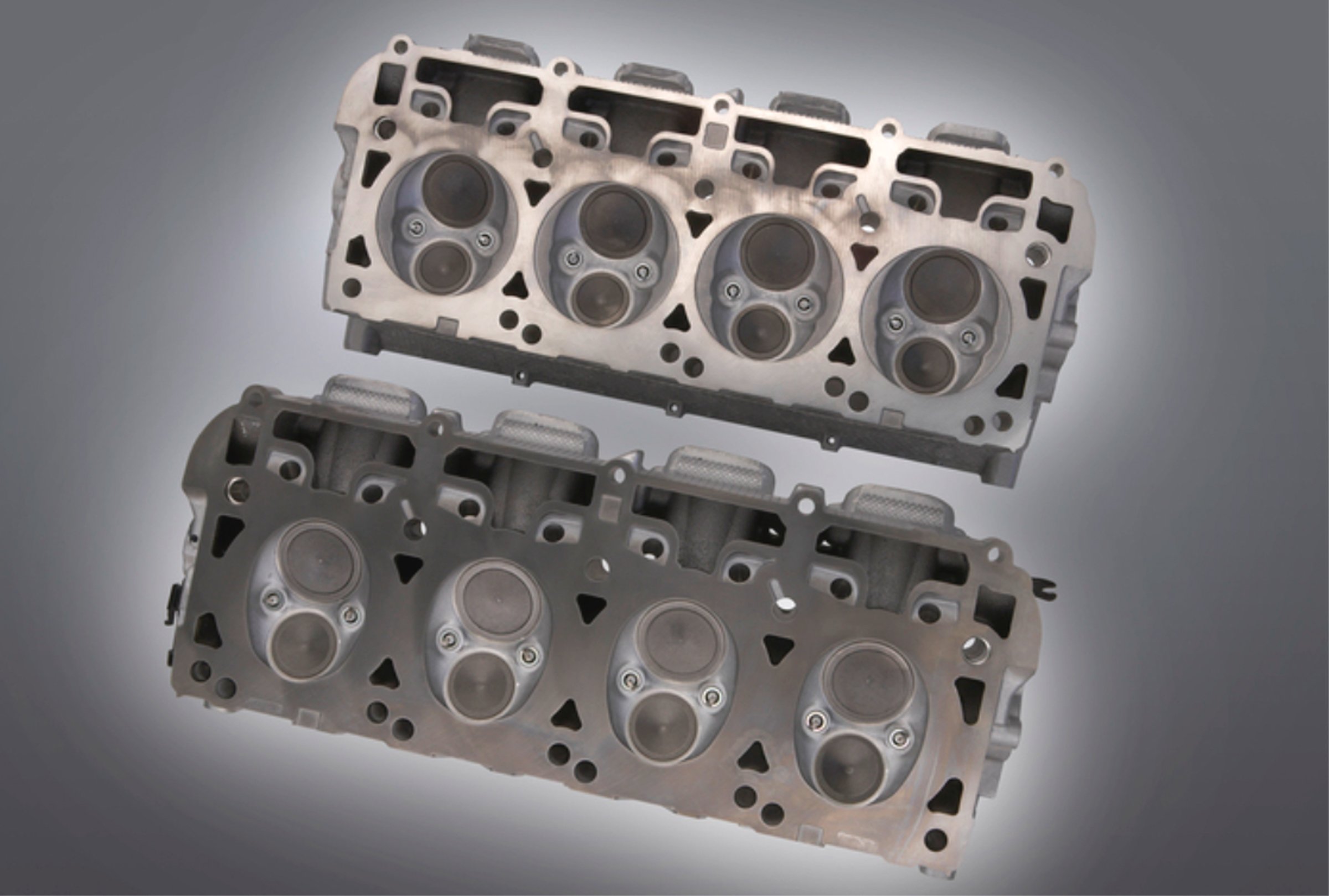
Early Gen III Hemis like the 5.7L used a full round chamber (top) while later engine packages evolved into an oval chamber that narrows the width, reducing the volume.
Here’s where all the attention is focused. We all know that engines are just big air pumps and nothing improves power like a good set of cylinder heads. In that light, the hemispherical chamber design has always approached valve placement with the idea of maximizing potential airflow. The opposed valves sit across from each other top to bottom as opposed to side-by-side in a wedge style cylinder head. There have been multiple changes throughout the Gen III production run with four different cylinder head configurations that encompass plenty of specific twists and turns.
The initial 5.7L engines employed an impressive rectangle port head with decently sized intake and exhaust ports and a round, but not quite purely hemispherical combustion chamber. The leading and trailing edges of the chamber were flattened to create small quench areas to improve combustion efficiency. To reduce ignition timing requirements across the large chamber, Chrysler added a second spark plug. Both plugs fire simultaneously.
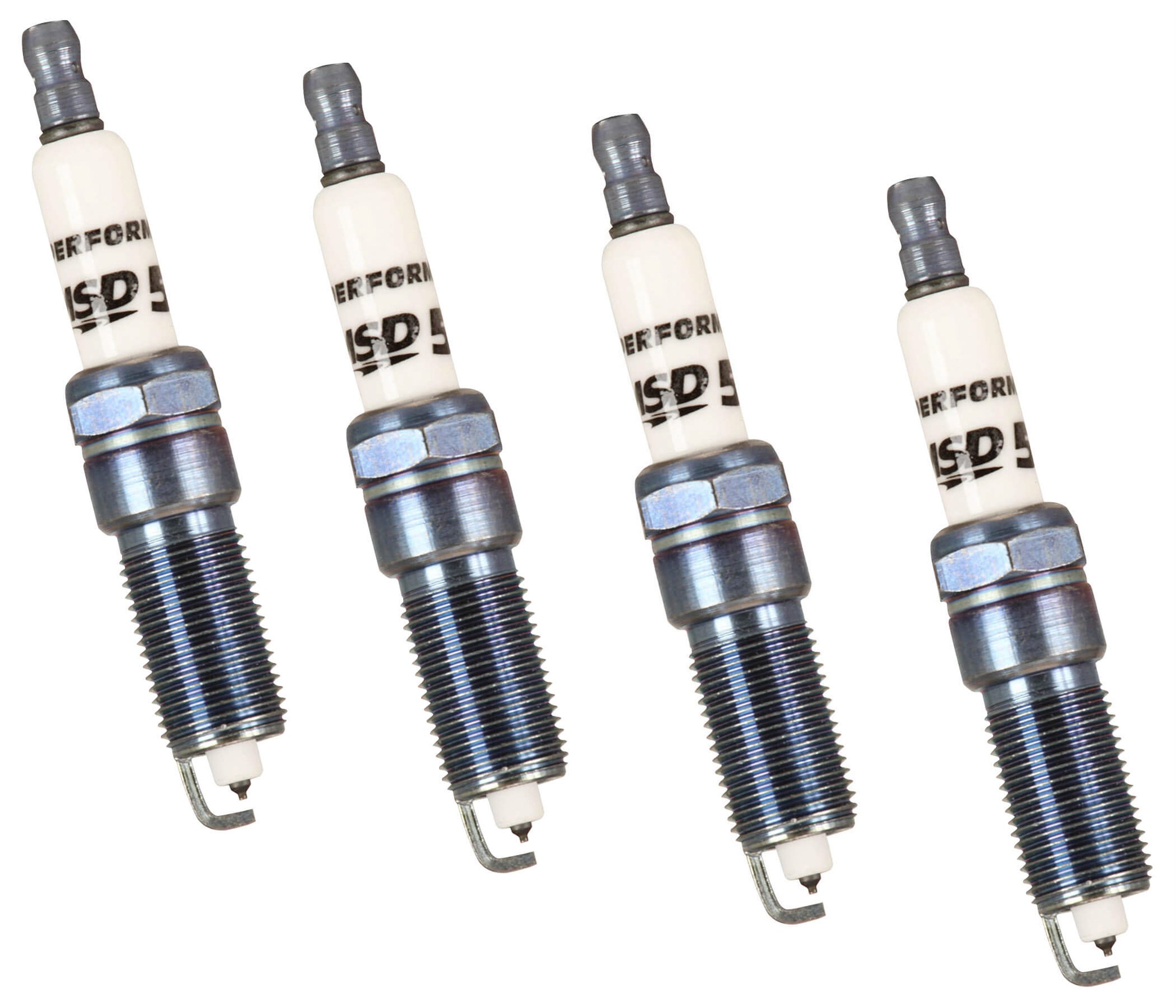
In order to reduce hydrocarbon emissions with a large hemispherical chamber, Chrysler added a second spark plug. So when it comes time for a plug change – remember you will be buying 16 instead of just 8. Note the reach (the threaded portion of the plug) is extended measuring 1.040-inch. MSD now offers Iridium spark plugs for the Hemi. Based on application the Hemi uses either a tapered seat (shown) or a gasket style seat.
The Hemi valve layout is an invitation for huge intake valves that would come later while the initial small-bore 5.7L engine was fitted with conservative 2.00-inch intake and 1.55-inch exhaust valves in an 85cc chamber. The 5.7’s small ports flow impressive numbers for their size achieving 280 cfm on the intake side. But that was just a first blush.
The 2005 SRT 6.1L is the only other Gen III engine to use the early, open chamber configuration. But there were further changes. The 6.1L chamber size dropped from 85cc to 74cc to increase compression but also improved airflow with larger ports and 2.075- and 1.88-inch valves. Flow numbers are around 320 cfm which is a substantial improvement over the earlier versions. The valves on these heads also expanded in overall length slightly to 4.90-inch for the intake and 4.89-inches for the exhaust.
The big evolutionary change occurred in 2009 when Chrysler instituted VCT. This change also allowed the opportunity for multiple cylinder head revisions. Starting from the inlet side of the head, the intake ports increased in size that also required an intake manifold bolt pattern revision. This means that Eagle intakes do not directly interchange with earlier 5.7L. There are adapters that will allow crossbreeding when necessary.
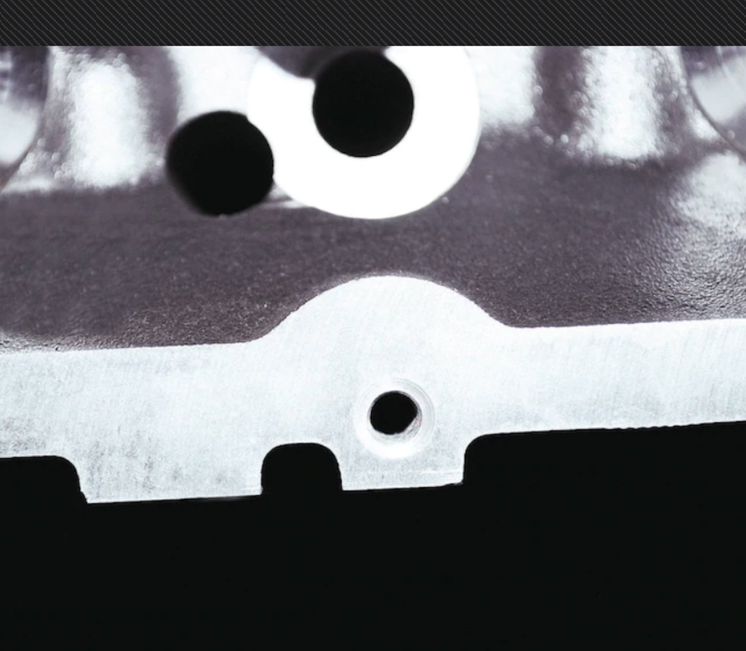
The 2009 and later 5.7L Eagle head with larger, revised ports can be easily spotted on an assembled engine by this notch in the lower portion of the valve cover rail.
The basic Eagle head configuration was used on all the remaining engines. The 6.4L Apache and the 6.2L heads are unique to their applications. According to our sources, even the core sand used for these heads is of a “finer” variety that improves as-cast port flow by one percent. There are also changes in valve seat materials and dimensions for these engines. The Eagle 5.7L intake ports are technology transfers from the SRT 6.1L engines and expanded with a much wider port entry and slightly larger 2.05-inch intake valves while the exhaust remained the same at 1.55-inch. Other changes included longer valves than the first version heads, which necessitated taller cast-in rocker stands along with pushrod length.
The SRT-designed heads destined for the 6.4L Apache 392ci engine enjoys the largest valve sizes at 2.14 / 1.65-inches – which are the same size used in the supercharged Hellcat and Demon packages. The Hellcat engines employ unique 356 T-6 alloy castings derived from the BGE 6.4L production designs. All SRT Gen III Hemi engines benefit from hollow-stem intake valves to reduce valve weight with sodium-filled exhaust valves to handle the additional heat.
The significant change for the Eagle head architecture is the “closed” chamber design that narrowed the width of the chamber creating an oval shape. This reduced the chamber size from 85cc to a far more compact 65cc. This chamber re-shaping is a big reason why the second generation heads are more desirable from a performance and efficiency standpoint.
The large intake port Apache heads employ yet a lengthier valve to allow additional lift and are fitted with taller valve springs that demand a greater installed height. However, as the accompanying chart indicates, there are multiple installed height specs for the 2009 and later engines. The extended installed heights for the 6.2L and 6.4L engines required longer pushrods to maintain the proper valvetrain geometry.
A significant Gen III Hemi detail that demands close attention is that all production Gen III heads use dedicated left and right side specific castings. That’s not a misprint. These heads are machined specifically as left or right side only and even though they will bolt on the block, there are specific machining operations that make them left or right. The exhaust bolt patterns for the center two exhaust port flanges are different from left to right. We’ve illustrated this pattern in an accompanying photo.

Chrysler machines its production heads as dedicated left and right castings. The main difference is the way the center exhaust port flanges are drilled for the exhaust. OE heads are only drilled with two bolt holes per exhaust port. This Edelbrock Gen III Hemi head is drilled with four bolt holes for each port to allow the heads to be interchangeable. The center two exhaust ports are the ones that differ side to side. On production heads, the holes marked “1” are the Left (driver) side configuration while the “2” holes are the passenger side.
But that’s only half the story. A main reason for the dedicated left and right heads may be to ensure that the oil drain holes in the heads are aligned with the returns holes in the block. All heads are cast with four drain-back holes but only three are machined to allow oil to drain back into the block. The front drain-back hole on each side is left un-machined. Aftermarket heads, like Edelbrock’s Gen III heads are drilled with four bolt holes in each the exhaust port to allow those heads to be interchangeable.
Hemi head gaskets are also “left” and “right” specific to ensure the rear drain back holes are not blocked. On production heads, the rear drain-back holes are machined so reversing the heads would block the oil from returning.
In keeping with the myriad of details involved with the Gen III’s evolution, you should be aware that along with the fact that the Hemi requires two spark plugs per cylinder, there is also a change in spark plug design. Early 5.7L and 6.1L engines were fitted with tapered seat plugs while the ’09 and later heads like the Eagle 5.7L, 6.2L and 6.4L are machined to accept a gasket style plug. Both designs use a very long threaded portion call the reach.
Another important point is that, as with most modern production engines, the head bolts are torque-to-yield style bolts that are intended as one-time use only bolts. Thankfully, they are affordable but if you plan on abusing your Hemi with lots of tear-down in between, you’re money ahead to invest in a set of ARP head bolts that can be re-used indefinitely.
CAMSHAFTS
Most factory Gen III Hemis use a nodular iron hydraulic roller camshaft. The ‘03-’08 first version engines employed the classic cam and crank gears and chain drive assembly that uses a specific cam core. This changed in 2009 with the addition of variable cam timing (VCT). This revision not only necessitated changes to the block, but also placed a VCT cam sprocket assembly bolted to the front of the revised camshaft.
Only three years after the initial introduction of the Gen III Hemi, Chrysler added the Multi-Displacement System (MDS) on 5.7L engines in 2006. This system utilizes four solenoids that direct oil to both intake and exhaust lifters on four specific cylinders. With a command from the ECU, pressurized oil is directed to each of these lifters that engages a pin that disables the lifter. The lifter still follows the camshaft lobe, but this system creates what has been called a lost motion device where the lifter moves but the pushrod does not. The valves in each of these deactivated cylinders do not open, creating a four-cylinder engine when power demand is low.
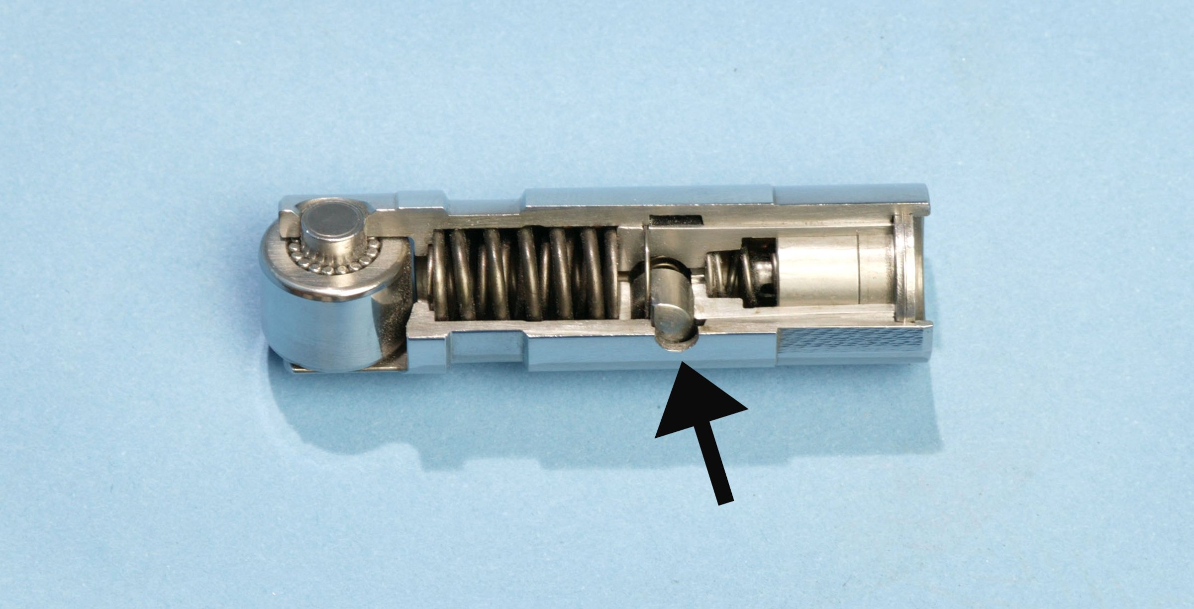
This Chrysler cutaway photo reveals the inner workings of the MDS lifter identified by its large internal spring. You can quickly spot an MDS lifter by the hole for the external pin (arrow).
The cam lobes for the MDS cylinders are different from the non-MDS cylinders, making the camshaft unique for MDS engines with multiple variations for different applications. For a performance application, aftermarket cam companies recommend disabling the MDS and replacing the original lifters with new non-MDS lifters. Later model lifters for the 6.4L engine appear to be the best production lifters for a performance application or even as replacement lifters for stock engines.
In VCT applications where the factory ECU will be retained, a performance camshaft change will often be accompanied with a VCT phase limiter or lock kits. The factory phaser has a broad timing range of 37 degrees. But with a longer duration and higher lift performance cam, this will create valve-to-piston interference problems. So several companies like Comp, sell a phase limiter that will reduce the cam movement to 14 crankshaft degrees (7 cam degrees).
With the conversion to VCT, the cams for these engines employ a completely different cam core assembly with a much longer front cam bearing journal that includes two annulus grooves cut into the journal to supply oil to the phaser mounted on the front of the cam that controls the VCT. Of course, this means that early cams cannot be interchanged with 2009 and later versions as they physically will not fit the block. So this negates any idea of using a more aggressive 6.4L Hemi cam in an early 5.7L truck engine, for example. However, all VCT engines use the same cam journal sizing so these cams can be interchanged which offers opportunities to place a more aggressive cam in 5.7L truck engine from a passenger car application. This means, of course, avoiding the use of any MDS camshafts.

There are multiple versions of the factory Hemi camshaft. This is a VVT camshaft that is quickly identifiable by the three grooves cut into the front journal. Non-VVT cams delete these grooves.
In the early ‘03-‘08 5.7L and SRT 6.1L engines, the camshaft is retained with a small 4-bolt plate and the timing chain assembly also used a specific tensioner and guide system. This was necessary because of the greater distance between the cam and crankshaft. With the redesign in 2009 and VCT, the front cam retainer plate became larger, retained with four bolts, and the tensioner and guide system was also changed. These systems are not interchangeable as they are specific to either early or late cylinder blocks.
Cam timing numbers (see chart) may appear long in duration compared to other OE cams. For example, the 6.4L 392ci Apache camshaft offers 286 degrees of duration at 0.006-inch tappet lift. This is often referred to as “advertised duration” as opposed to duration at 0.050-inch tappet lift which will always be 60 degrees or more shorter because of the measuring point taken after the lifter has achieved 0.050-inch of lift.
Some of this longer cam timing can be attributed to VCT – or variable cam timing. With VCT, the computer can advance or retard the camshaft position through as much as 37 degrees. Long duration cams tend to sacrifice low-speed torque due to a late-closing intake valve. But by advancing the camshaft, a portion of that lost torque can be restored. Then at higher engine speeds, the ECU can retard cam position, allowing the engine to take advantage of the late intake valve closing point.
When the VCT system was included in the 2009 and later engines, this also required all new timing components including a revised sprocket drive on the crankshaft, and a complete upgrade of the cam drive components. Among the items of issue with the Gen III Hemi has been failures related to hydraulic lifters. If MDS engine lifters are changed, this also requires a change to the holder that retains the lifters and the design is different between the two lifters configurations.
VALVETRAIN
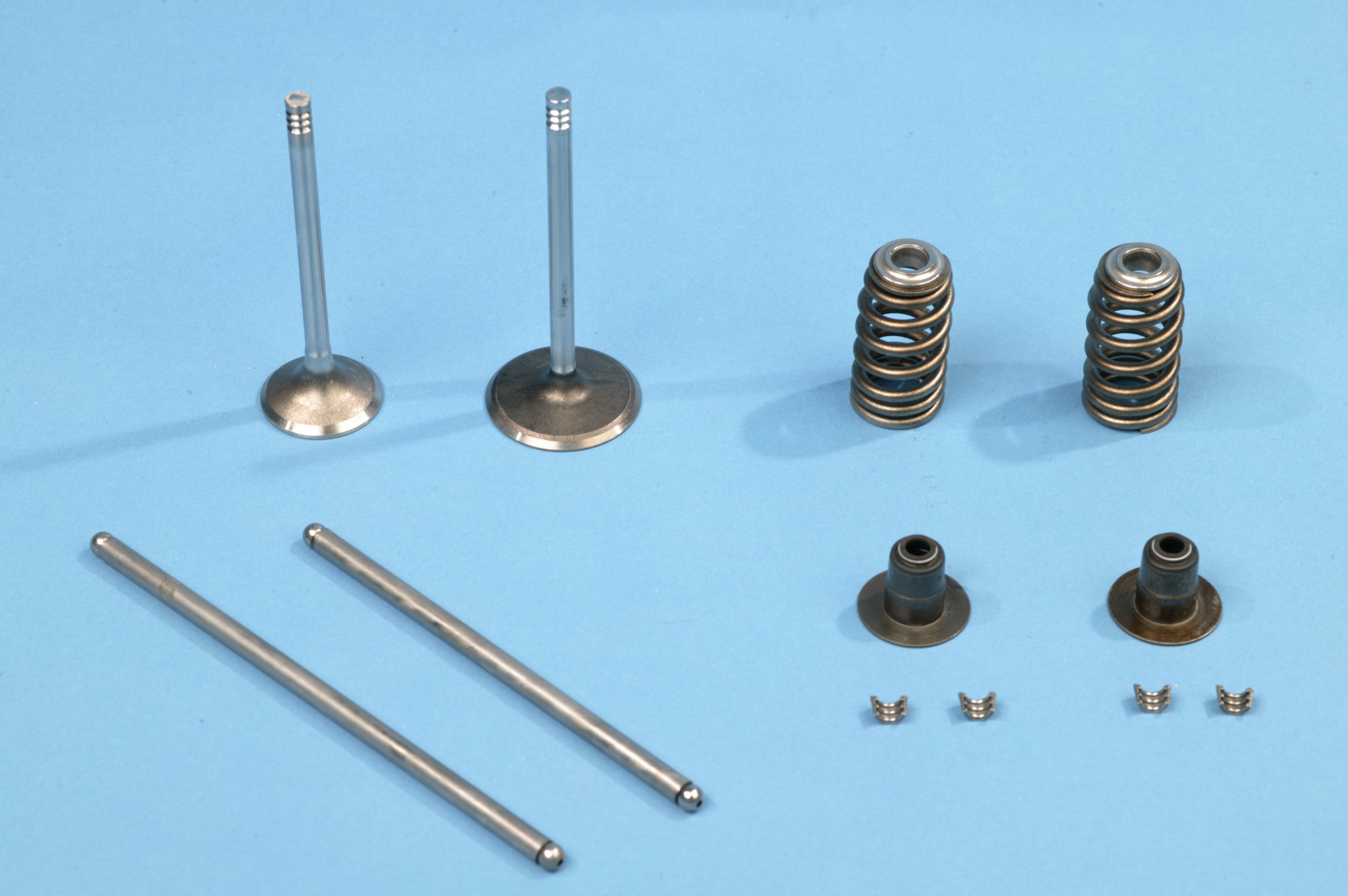
All Hemis use beehive valve springs and there are multiple spring combinations based on application and installed height. Because of the valve layout of the Gen III Hemi, there are two different length pushrods. The longer versions are for the exhaust side and lengths will change for different configurations.
The early 5.7L engine design carried over the Gen II Hemi’s design that used separate rocker shafts for the intake and exhaust. After the early 5.7L established these positions, the 2009 and later 5.7L Eagle, 6.4L, and 6.2L engines raised the rocker stand height slightly to accommodate the longer valves. The cast-in stands in the newer heads raise the shaft about 0.200-inch and the stand positions were widened roughly 0.140-inch.
These longer valves were created to allow greater valve lift which in turn required a taller valve spring and installed height. The 6.2L Hellcat and 6.4L Apache heads enjoy an increased installed height even over the Eagle 5.7L heads because of longer valves.. Installed height is defined as the distance between the valve spring seat and the underneath side of the valve spring retainer. A taller installed height allows sufficient real estate to allow for more valve lift height but does require a longer valve spring.
This is reinforced in our cam specs chart where the 6.4L Apache camshaft creates nearly 0.100-inch more intake valve lift than the early 5.7L engine. The more aggressive 6.4L Apache cam would not work in an early 5.7L engine because the springs will coil bind causing massive damage. Of course, adding a set of Apache heads to the 5.7L engine will alleviate these problems, but there are other compatibility issues that also need to be solved to accommodate that swap.
Among the details a Gen III Hemi engine builder must keep in mind is the fact that the rocker arm ratio is not the same between the intake and exhaust sides. The intake rocker ratio is 1.60:1 while the exhaust side uses a higher 1.66:1ratio. Theoretical valve lift is computed by multiplying the lobe lift on the camshaft by the rocker arm ratio. So if the intake lobe creates 0.3568 inches of lift multiplied by 1.60 equals 0.571-inch which is the 0.571-inch factory intake lift number for the 6.4L 392 engine. All intake rockers are marked with a capital “I” to prevent confusion. The exhaust rockers are not marked.
The rocker shafts themselves are completely interchangeable throughout the entire Gen III family tree. According to our Chrysler contacts, lubrication, surface treatments, and friction reduction improvements make the late model shafts highly desirable.
Another important point is that as rocker stand heights and installed heights become taller, this also requires a longer pushrod. Standard Gen III engines all use a 5/16-inch diameter pushrod but the length will vary with each successive increase in installed height. The Gen III shaft rocker system does not allow for adjustment so hydraulic lifter preload is set by the pushrod length. We’ve included a chart that lists all of the production valve spring installed heights to indicate the number of changes throughout the Gen III’s evolution.
Given these multiple installed heights, this also means specific valve springs are required for each different height. The simplest way to approach this is to measure the head you are working on and then approach a performance spring selection based on this installed height. All Gen III heads use a beehive style valve spring and there are multiple aftermarket companies offering performance springs.
Factory Gen III Hemi lifters are all 0.842-inch in diameter and there have been issues with durability in early engines. Early lifters suffered from retaining clips that came apart but this could be traced to loss of valvetrain control from over-revving or valve float.
The BGE engines have also benefited from a redesign of the lifters that is now standard on all production Gen III Hemis. The lifter axles and bearing needles have been subjected to carbon-nitriding and also have been cryo-stabilized. All of this contributes to a stronger lifter and is completely interchangeable with all Gen III Hemi variants. These are the lifters that should be included with any performance camshaft upgrade. We found part number 05038784AD under Mopar lifters in the Summit Racing catalog that offers four lifters and a dedicated holder, which would require four of these PN’s for a complete set.
For any performance application, our sources tell us that the Demon / Redeye engine uses that redesigned lifter along with a 5150 steel camshaft core that raises the bar in terms of reliability. The entire valvetrain has been validated to the equivalent of 300,000 miles of WOT operation at 6,300 rpm. This is the equivalent of 12 trips (plus some!) around the world at the equator at WOT with no lifting! What does that tell you?
LUBRICATION SYSTEM
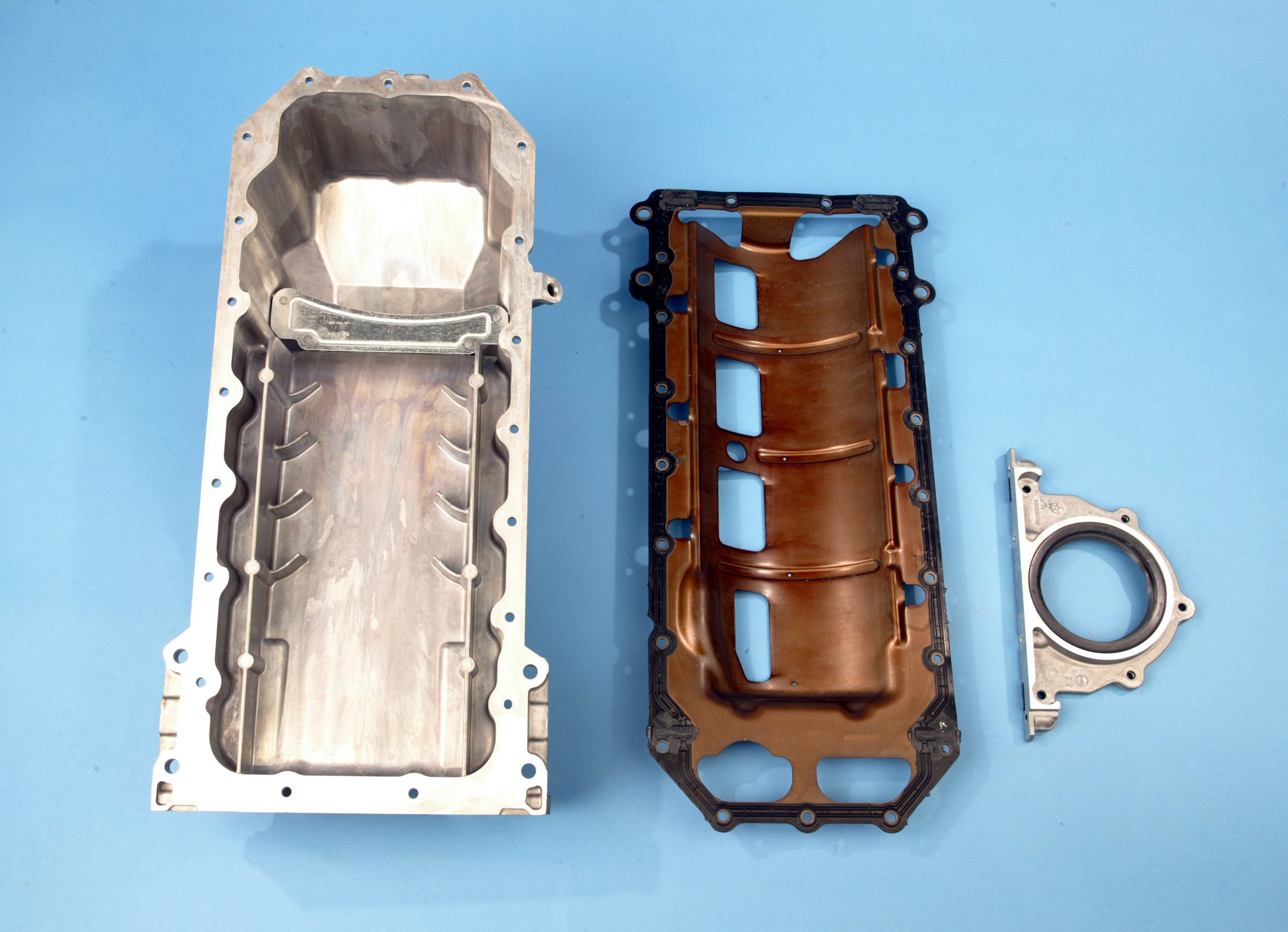
All Gen III Hemi engines use a pan gasket that also doubles as a windage tray. This photo is of an early 5.7L engine. With three different stroke cranks, there are also matching trays for each variation.
Compared to previous small-block Mopar engines, the lubrication system is vastly different. Since the Gen III does not employ a distributor, engineers mounted the oil pump on the snout of the crankshaft driven by a splined collar that fits over the crank. This changes oil pump operation because now the pump is driven at engine speed instead of half engine speed as with previous engines.
The oil pump is a gerotor design intended to operate much more efficiently than the older spur gear pumps of previous generation engines. A longer pickup tube is now required, especially for rear sump engines.
There are several oil pump revisions to the early Gen III engines but the most significant change occurred when Chrysler redesigned the Gen III for VCT. Control over VCT is accomplished with hydraulic pressure and oil volume, so the VCT oil pump has a 22 percent larger capacity and is significantly deeper than its predecessor. The pickup tube and inlet into the newer pump are also larger to accommodate the increased volume demand.
Because the added VCT drive on 2009 and later engines moved the cam drive assembly forward, the late model oil pumps are also shifted forward. While the actual oil pump bolt pattern is the same between all the pumps, the newer, higher output pump cannot be used on the non-VCT engines. Melling does offer a line of high performance pumps for all the different variations on the Gen III Hemi.
The pump pushes oil into the main galley that runs down the middle of the block. This latest Hemi oils the engine in a similar fashion to other V8 engines in the first part of the circuit. The main oil galley that is fed oil from the filter runs front-to-back with passages feeding downward to the main bearings (and rods) and upward to the cam bearings.
A third passage off the main galley is connected directly to the cylinder heads through the block. Oil is routed through the rocker shafts to lube the shaft bushings, the rocker arms, top of the valves, and pushrod tips. This circuit also feeds oil down through the pushrods down to the hydraulic roller tappets. This makes for a rather circuitous path that places oil into the lifter body as the farthest point from the origin at the oil pump.
For MDS engines, there are four solenoids in the lifter valley cover that control the four cylinders. These solenoids control the operation of the MDS lifters. As mentioned earlier, any change to a performance camshaft should also include replacing the MDS lifters.
INTAKE MANIFOLDS
In keeping with current trends, almost all of the factory Gen III Hemi intakes are constructed out of a modern plastic. The only exception is the short-lived 6.1L SRT8 manifold that was cast in aluminum. All factory intakes are fitted with electronically controlled throttle bodies. This means there are no original equipment, cable-actuated throttle bodies although there are aftermarket throttle bodies available. In addition, all the normally aspirated engine throttle bodies (except for the 6.4L 392 engine) measure 80mm. Because of the increase in displacement, the 6.4L and the supercharged Hellcat 6.2L engines use a larger 92mm throttle body.
Starting with the early truck engines, this plastic intake will only bolt up to the ’08 and earlier 5.7L engines. A separate intake appeared when Chrysler began putting the 5.7L engine into passenger cars with a lower hood line that required a shorter manifold. This design is often referred to as a barrel or beer barrel manifold because of its lateral ribs. As mentioned, when the 6.1L SRT8 engine appeared this short-run engine utilized an aluminum intake manifold and is universally considered the best flowing manifold of all early factory intakes. Unfortunately, this manifold is no longer in production and, like all highly sought-after factory parts – are difficult to find and expensive.
When the redesigned Eagle engine appeared in 2009, the revised intake ports also demanded a different intake bolt pattern so later Eagle intakes will not directly bolt onto the earlier heads. The car manifolds also have a barrel shape based on the runner design. There are several companies now making adapter plates that allow interchange between the early and late port designs. Truck manifolds tend to use a vertical facing throttle body while the better flowing passenger car versions use forward-facing 80mm throttle bodies
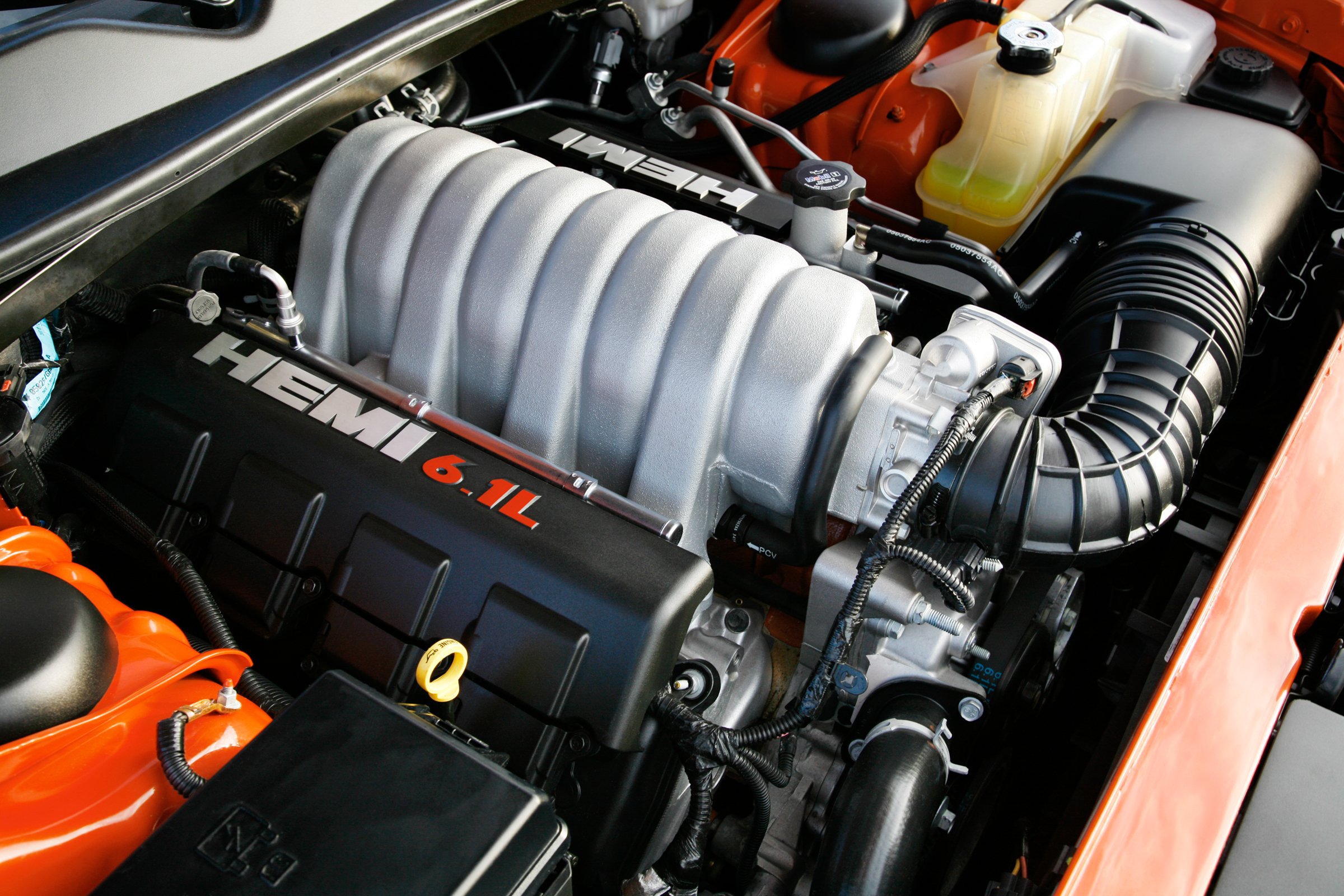
The word on the street is that among the production intake manifolds, the 6.1L SRT8 aluminum casting seen here is the best of the bunch, but with a rather short production run, finding one may be – shall we say – a challenge.
Until the production of the larger normally aspirated 6.4L Apache and supercharged 6.2L engines, all passenger car manifolds oriented the throttle body straight ahead. In the Apache 6.4L intake, the throttle body is redirected toward the driver side of the vehicle at a 45-degree angle to improve air movement into the inlet.
The BGE 6.4L truck engine is acknowledged as the optimal production manifold for the Eagle series and our sources tell us that these “active” manifolds are worth roughly around 12 hp over 6.4L Charger and Challenger 6.4L Apache SRT active manifold versions. The “active” manifold design uses an internal valve that can switch between short and long-runner lengths. These are often referred to as Short Runner Valve (SRV) manifolds because during low-speed operation the inlet air follows a longer path to build low-speed torque. But when demand increases, a valve opens and a “shortcut” passage is created to reduce the runner length and enhance top-end power.
Fuel injectors are another bit of information that fluctuates with the different Gen III Hemi performance and displacement variations. We’ve included a chart that lists the sizes rated in both cc/min and pounds per hour (lbs/hr) of fuel. All factory injectors are high impedance units that operate at a 58 psi rail pressure, except for the supercharged engines which boost reference the pressure to compensate for high manifold pressure.
SUPERCHARGERS
Things really got interesting when Chrysler debuted the Hellcat engine in 2015 with an IHI screw supercharger bolted to the top of the engine. The blower is unlike other superchargers used by the OE’s in that these are true screw superchargers. This design actually operates as a true air compressor. Other blowers like the Roots and even helical-twist superchargers like the Eaton/Magnuson are air movers and not true compressors. Blowers merely move enough air to create pressure in the intake manifold – creating boost. A true compressor creates internal compression.
The difference may seem insignificant, but the difference was enough to suggest to Chrysler engineering there was a performance advantage by choosing a screw compressor. In the case of the 6.2L Hellcat engine, the supercharger uses three male and 5 female lobes. As the air travels through the area between these 2.4L lobes, the air is gradually squeezed, creating pressure. As the blower turns one revolution, it moves the equivalent of 2.4 liters of air.
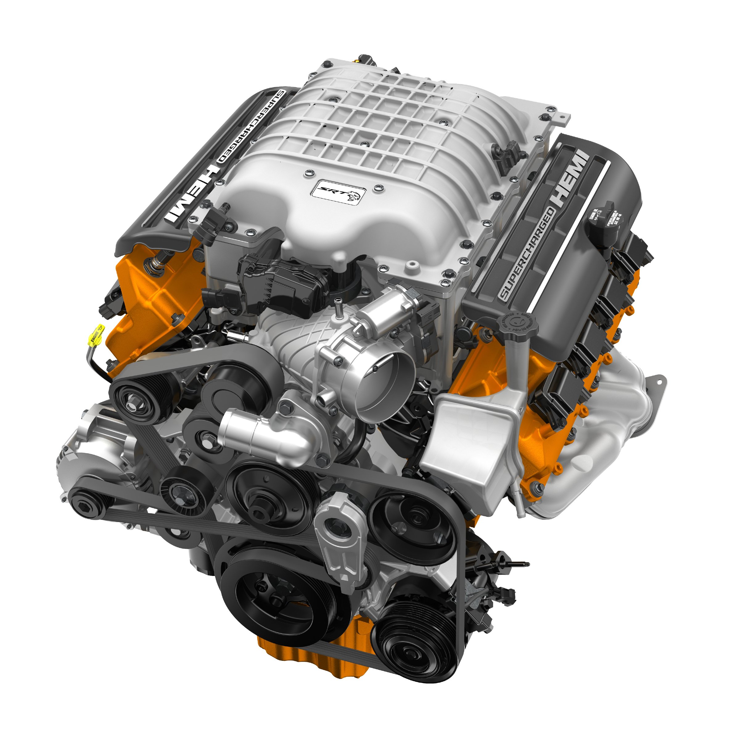
The Hellcat is Mopar’s entry into the high-horsepower arena. With a 2.38L IHI twin-screw supercharger making nearly 11.6 psi of boost, this engine is factory rated at 707 horsepower on pump gas. But it’s the massive torque created by the supercharger that really helps acceleration.
The supercharger is designed and built by IHI and is housed in a cast aluminum body that sits above a stack of two separate intercooler “bricks” that circulate cooling air to reduce the discharge temperature. The Hellcat is rated at 707 hp on 91 octane pump gas using this “small” supercharger. With inlet airflow critical to performance, Chrysler also increased the size of the throttle body to 90mm and with 100 octane race gas, this package is capable of 797 hp. To help with durability, the rotor packs are coated with a PTFE and a polyimide resin coating which reduces friction and thereby heat, which is always a plus. According to SRT sources, this coating is sacrificial, which allows the rotor set to bed in, creating a near-zero clearance for increased efficiency.
The horsepower race was on and it didn’t take long to create a bigger version of the Hellcat engine with the Demon upgrade two years later. The main ingredient in the Demon package is a slightly longer version of the 2.4L supercharger, spec’ing in as a 2.7L piece that can move much more air for each revolution of the supercharger.
But even that wasn’t enough. Available only as a crate engine package through Mopar Performance, the Hellephant is a larger, 426ci supercharged package that carries yet an even larger 3.0L screw supercharger that’s capable of making an astonishing 1,000 horsepower and 950 lb-ft of torque on 91 octane pump gasoline. And just in case that wasn’t enough, the Challenger SRT Demon 170 bumps that power figure to 1,025 horsepower.
CONCLUSION
As with any production V8 engine, the Gen III Hemi offers tremendous potential for V8 engine swappers in terms of later model performance for a reasonable price. Now that we’ve covered the basics of the breadth of the production engines, the next step for the Mopar performance enthusiast is to decide which engine offers the most potential power per dollar invested. Financial people call this Return on Investment or ROI.
We’ll save that discussion for a follow-up story but certainly the ’09 and later engine with their superior cylinder heads would appear to be the wise move, but there are plenty of opportunities for swapping Eagle style heads onto earlier 5.7L engines – especially if there is enough money in the engine building fund for a stroker crank and a displacement increase.
A few years ago, the Engine Masters program attracted a few noted engine builders that saw a couple of normally-aspirated 400ci 5.7L-based engines push horsepower out to between 690 and 710 hp. Granted, these efforts are acknowledged as really closer to pure competition engines. A quick way to tell a motor that make excellent power is to look at the engine’s torque-per-cubic-inch expressed as lb-ft/ci. Late model street engines can often achieve 1.25 to 1.35 lb-ft/ci. The aforementioned 400 ci Engine Masters Gen III Hemis worked that number up to 1.53 lb-ft/ci. On a 400 ci engine, that’s over 610 lb-ft of torque – which is plenty impressive.
